
Nearly two thousand years ago, Rome’s eleven aqueducts moved an estimated 400 million cubic meters of water into the city each year, relying solely on precise gradients and masonry construction that partially stands today. A useful question I want to explore is: can that same system can be replicated into a modern American city? This paper examines whether Rome’s ancient aqueducts could meet the water demands of greater Seattle. By completing an analysis on how much water the infrastructure delivered annually compared with the city’s average municipal water consumption, it can be understood how feasible a project like this can be in the modern day. This paper also analyzes the system’s differences from today’s water standards and analyzes the benefits and drawbacks from it. To do this, the paper first outlines how Rome’s aqueduct system functioned, calculates what capacity they operated at, compares Roman water quality to modern treatment standards, and finally evaluates whether a similar system could feasibly serve Seattle.
Rome’s Aqueduct System
As Rome expanded into the capital of the Roman Empire, its population and demand for water increased substantially as historians estimate near one million citizens during Augustus’s reign (Deming, 2020). Supplying this required more than water for drinking and basic household use, as it was essential for many aspects including public fountains, bathing, gardens, and industrial activity. Public fountains were also an important component of the urban water supply; Frontinus, the Roman water commissioner, recorded 591 public water basins in first-century Rome (Frontinus, trans. 2003, p.13).
According to Frontinus, Romans relied on water sources like the Tiber River, wells, and natural springs within the city for the first 441 years following the city’s foundation (Frontinus, trans. 2003). Eventually, the growing demand for water exceeded the supply of these sources, leading to the construction of the first ancient Roman aqueduct: Aqua Appia. Led by emperor Appius Claudius Caecus in 312 BC, this marked a major change in Rome’s approach to water supply, allowing water to be transported from Praenestine Way Estate through a controlled system (Frontinus, trans. 2003). Over the following five centuries, Rome continuously developed and redeveloped a network of eleven major aqueducts which can be seen together in Figure 1.
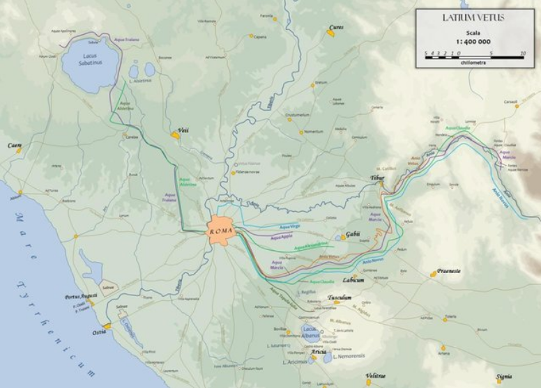
Before continuing, it is worth noting the names of the aqueducts came from several different aspects of their water source and history. The Latin term aqua means “water”, and was mainly used. Anio, however, identifies aqueducts associated with the Anio River. The Anio Vetus and Anio Novus were both supplied from the Anio, with vetus meaning “old” and novus meaning “new.” The names of the aqueducts can also identify their builders, associated families, geographic sources, or their relationship to earlier infrastructure rather than following a single naming convention.
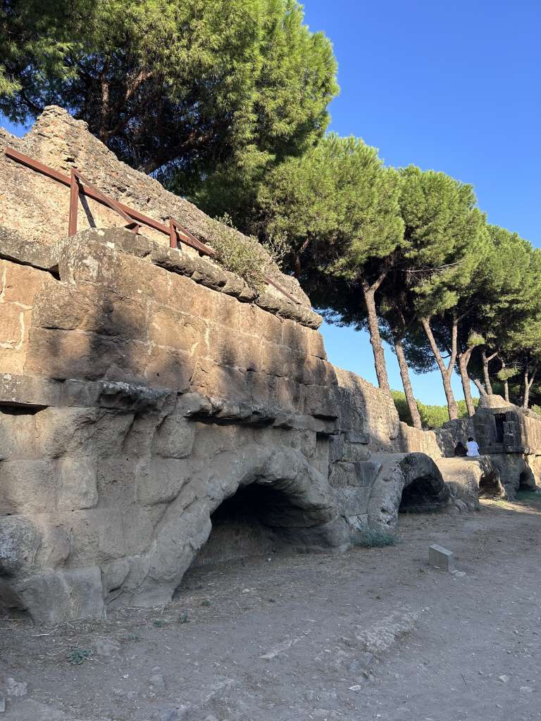
Anio Vetus was the second aqueduct constructed, between 272 and 269 BC, during the republican period of Rome and fed from an area above Tivoli. Unlike the spring-fed Aqua Appia, the Anio Vetus obtained its water from the Anio River. The third major aqueduct, the Aqua Marcia (Figure 2), was constructed beginning in 144 BC during the same era of Republican Reign sourcing from springs near Arsoli. Its name derived from its builder, rather than from its water source, and the aqueduct became particularly valued for its high-quality spring water. The Aqua Tepula (Figure 2) followed in approximately 125 BC, drawing water from the Alban hills and connecting to Aqua Marcia for its last 10 kilometers before it entered the city (Hodge, 2002).
A major expansion of Rome’s water infrastructure occurred during the transition from the Republic to the Empire. Marcus Agrippa, a leading general under Augustus, ensured extensive repairs to the existing aqueducts and constructed three additional systems: Aqua Julia (33 BC), Aqua Virgo (19 BC) (Figure 3), and Aqua Alsietina (2 BC) (Hodge, 2002). Frontinus says that Agrippa also constructed numerous fountains for the public, while also reconstructing the deteriorated Aqua Appia, Anio Vetus, and Aqua Marcia. Frontinus described the water from Aqua Alsietina as unsuitable for drinking, and it was primarily used for irrigating gardens and filling artificial lakes used for naumachiae, or staged naval battles. This was due to the fact that it carried water from Lake Alsietina instead of a spring, and the Romans believed stagnant water lacked movement, which was associated with decay, bad smells, and illness (Deming, 2020).
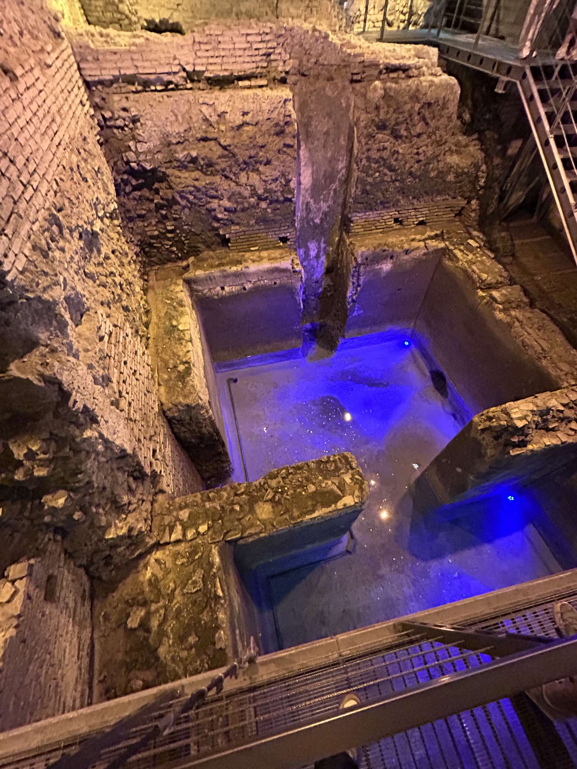
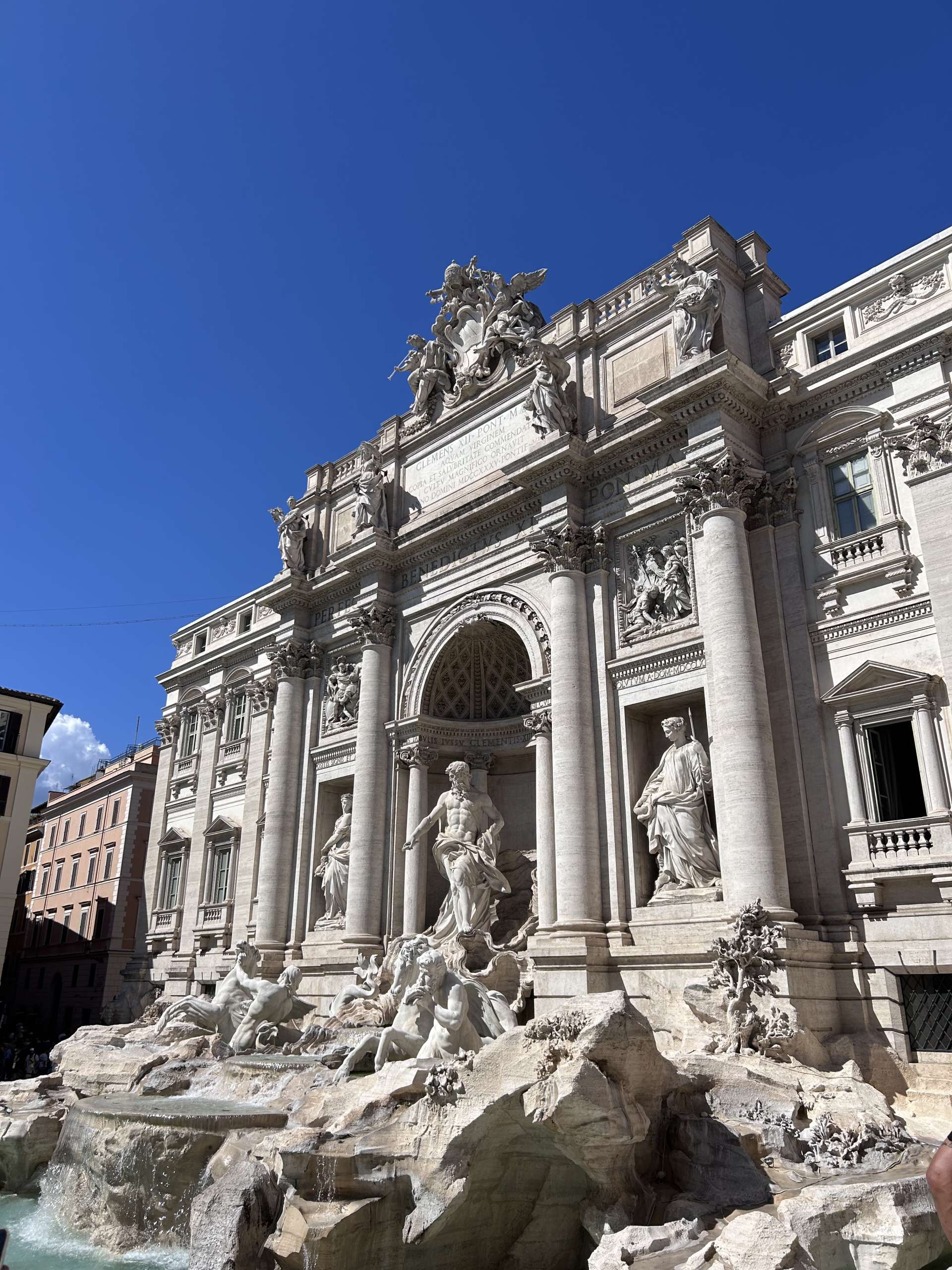
Surprisingly, one of the eleven ancient aqueducts is still running today: Aqua Virgo. Most of its channel stays hidden deep beneath the earth, protecting it from damage during wars and the collapse of the Roman Empire. It supplies famous monuments like the Trevi Fountain (Figure 4), the Fountain of the Four Rivers in Piazza Navona and the Barcaccia at the Spanish Steps (Roma Capitale, 2022).
The next major expansion occurred under Emperor Claudius, where the Aqua Claudia and Anio Novus were constructed from 38 to 52 AD (Figure 5). Aqua Claudia’s water was regarded as high-quality as it came from springs near Marano Equo, whereas the Anio Novus was supplied directly from the Anio River. Similar to Aqua Marcia and Tepula, the channel of Anio Novus was constructed directly above the channel of the Aqua Claudia as they entered the city (Hodge, 2002).
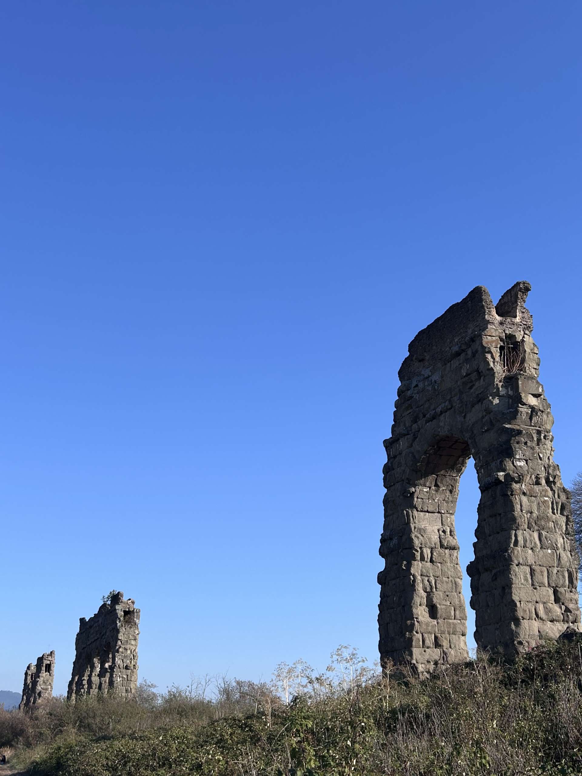
Two additional aqueducts were constructed after Frontinus’s life, so little recorded information on their characteristics still exists today. Emperor Trajan had the Aqua Trajana constructed in 109 AD, drawing water from springs near the Sabatine Hills and Lake Bracciano. Later in 226 AD, Emperor Alexander Severus had the last surviving aqueduct constructed, Aqua Alexandrina (Volterra, 2012). Its water originated near Pantano Borghese and was used to supply the enlarged Baths of Alexander. With the full network established, its physical components can now be examined.
The aqueduct network was more than a series of long channels, as it consisted of many structural components, each designed to collect, convey, control, or distribute water while maintaining a downward slope. The most important component was the specus, the enclosed channel through which water flowed. The specus was generally constructed of brick and cement, and was lined with a lining of opus signinum. This lining was an ancient waterproof mortar made from lime and crushed terracotta to help prevent leakage out the specus (Hodge, 2002).
Because the engineering of the aqueducts relied on gradual slopes, their routes were determined by topography and the location of the water source. The Romans constructed the underground channels wherever possible, in order to reduce the amount of needed material for construction. This protected water and reduced the amount of surface-level infrastructure. When the channel had to cross valleys/depressions, the Romans constructed arcades, or series of arches (Hodge, 2002).
When a valley becomes too deep/long to cross, engineers created inverted siphons which were more economically viable (Figure 6). Pressure created by the elevation difference at the low portion of the valley allowed water to rise and continue toward the city. Because the pipes had to withstand increased pressure, siphons were sometimes more demanding than ordinary arcade channels (Chanson, 2000).
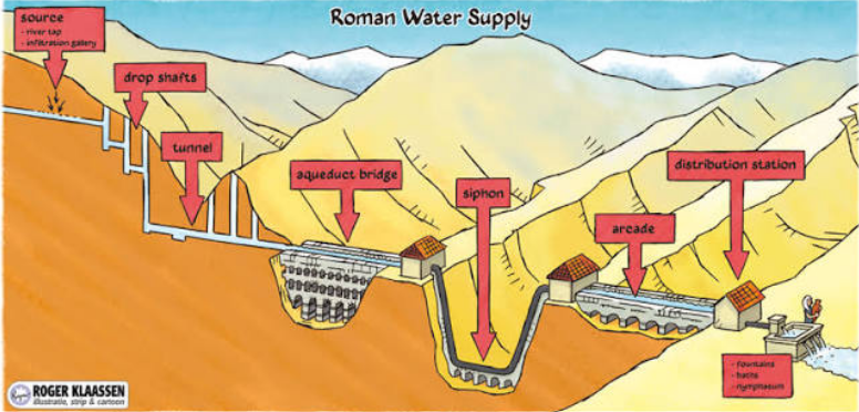
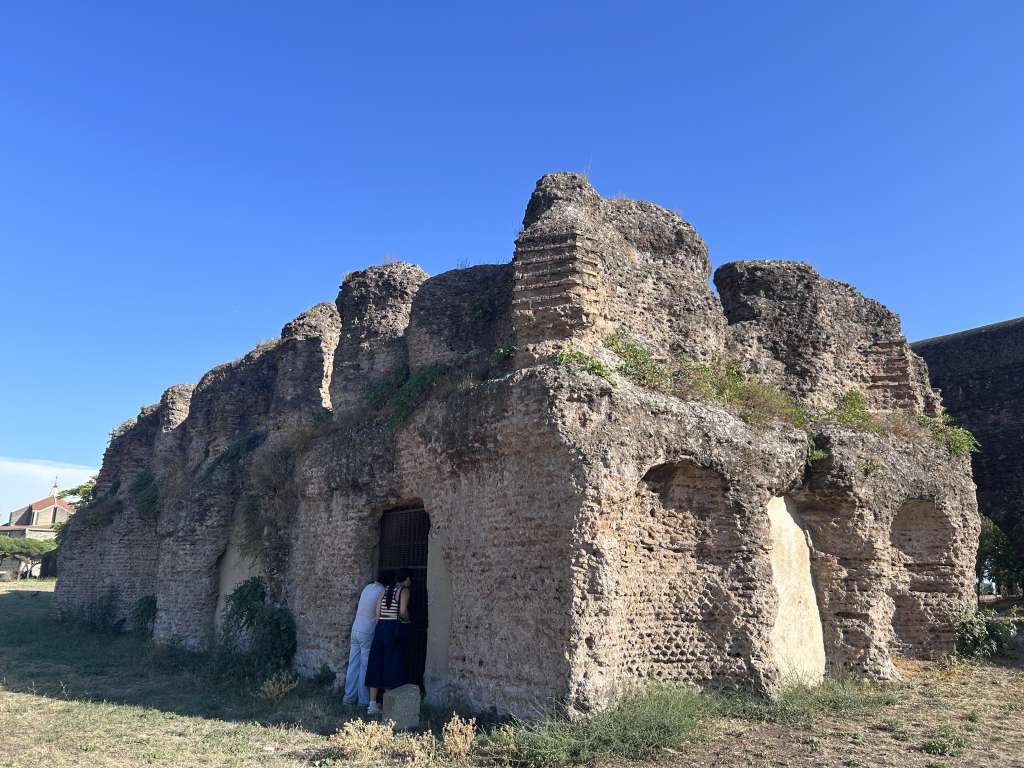
Water quality was also an important consideration, as settling tanks, or Piscinae limariae, were used to slow water and settle sediment before the water continued (Figure 6). This was important for aqueducts supplied by rivers because they could increase in turbidity during heavy rainfall (Hodge, 2002). The water would finally enter a castellum aquae at the end, which served as a distribution reservoir (Figure 7). From this structure, flow was divided into multiple channels and distributed throughout the city’s smaller pipes. These networks supplied fountains, baths, households, and gardens. Additional control structures along the aqueduct route allowed water to be regulated, diverted, or accessed for maintenance (Hodge, 2002).
Taken together, these components functioned as a single continuous system: water collected at a spring or river was channeled through settling basins, tunnels, arcades, or siphons along a gentle gradient, and finally delivered to users via a castellum.
Personal Observations
An observation I had during my experience visiting these aqueducts in Rome was that each aqueduct had distinct characteristics that separated it from the others, as they came in all shapes and sizes. The most noticeable differences to me were height, building technique, and state of preservation. While visiting Parco degli Acquedotti, Aqua Marcia was clearly the oldest structure to me, as it uses large, asymmetrical blocks of tuff. The blocks were finely cut to fit tightly together, and the structure stood much closer to the ground than the others. There was no visible mortar between the blocks, so I assume metal clamps were used to lock them in place as many holes were left behind in the block faces, similar to The Colosseum.
Aqua Claudia towered over the park and appeared to rely on concrete poured around its foundations rather than large fitted stone. There was some evidence of metal clamps, but far less frequently than Aqua Marcia. I also couldn’t find any clear joints anchoring the foundations into the ground, so it seems the structure was staying upright entirely from its weight.
Aqua Felix stands apart from both, as it uses a smaller brick for foundation, as well as a more circular arch design to make it look distinctly modern. There are also far less gaps in the remaining structure, showing how it had less time to weather away and preserve better. Aqua Claudia and Marcia both have numerous missing connections that were lost likely to earthquakes, war and material stripping.
What struck me more than any construction detail, though, was the sheer scale of what I was looking at. Walking underneath arcades standing 30 meters that still carry their own weight after two thousand years, and realizing that this was just one of eleven aqueducts feeding a single city, forced me to rethink my assumptions that I had while starting this project. Originally, I believed that due to population growth, increasingly efficient technology, and water usage, Seattle’s demand would be far greater than what could be supplied by Rome’s ancient technology. Seeing that scale in person began to put real doubt in my mind. Roman engineers were capable of moving water at a scale I hadn’t given them credit for. That shift is what sent me back to this project with a genuine sense of wonder to the overarching question, and motivated me to find the answer.
Health & Water-Quality Problems
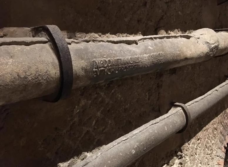
Having traced how water moved through the system, another question to answer is how well that water served the people. Judged from the standards of its time, Rome’s aqueduct network was a remarkable achievement in engineering and scale; however it has several problems when judged against modern public-health requirements. The first major issue was water quality and health protection. There were no modern treatment processes such as filtration, disinfection, or continuous microbial monitoring (Deming, 2020). In addition, water was distributed within Rome through extensive networks of lead pipes (Figure 8). Modern research has found evidence that water distributed through these pipes contained substantially more lead than local spring water. Under the modern drinking-water standards, the use of lead distribution pipes is considered unacceptable because it is a neurotoxin that builds up over time, causing neurological and developmental changes to children and pregnant women (Centers for Disease Control and Prevention, 2024).
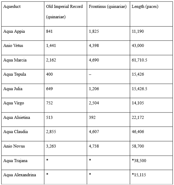
A second major limitation was water loss from system leakage. Frontinus, who investigated Rome’s water supply in the first century AD, found substantial differences between the quantities of water recorded in official records and the amounts he measured at different points in the system. He specifically attributed some of these differences to leaks in buried conduits, which were difficult to locate because they were underground. This is the same discrepancy shown in Table 1, where Frontinus’s measured discharge diverges from the older official records. He also identified unauthorized connections that diverted water from the public system. Maintenance was also difficult because repairs sometimes required terminated service of the aqueduct (Hodge, 2002). A modern analysis also shows that spring water used would coat the inside of lead pipes with a layer of calcium carbonate. This shows poor control of water and inadequate leak detection compared with modern systems.
The Roman system was highly effective at transporting huge amounts of water, but it lacked several layers of treatment, monitoring, leak control, and public-health protection that are fundamental to modern municipal water systems.Type your paragraph here
Calculation Methodology and Results
The following analysis helps understand exactly what design scale were the Romans using to create their aqueducts. Did they want them to be running at full capacity? Did they actually? This analysis helps understand the design components necessary to build the theoretical Seattle aqueducts similar to Rome. Table 1 combines recorded measurements of aqueduct flow by Roman authorities and Frontinus with modern calculations used to reconstruct lost info, in quinariae. A quinaria was a Roman unit used to express the discharge of water conduits (Hodge, 2002). Table 1 also reports the length of each aqueduct from Frontinus, in Roman paces. A Roman pace was a unit of length equal to five Roman feet, and a conversion of 1 pace ≈ 1.48 m was used to help future calculations in imperial units (Hodge, 2002). Values of the Aqua Traiana and Alexandrina utilize modern calculations because they were constructed after Frontinus died and do not have surviving records. Something interesting in the data is the gap between the recorded discharge values from Roman authorities vs. Frontinus. It reflects leakage and losses within the water system that Frontinus himself credits to being repaired by the empire, as well as interconnections made between aqueducts in order to help sustain water delivery if one ever needed repair (Frontinus, trans. 2003).
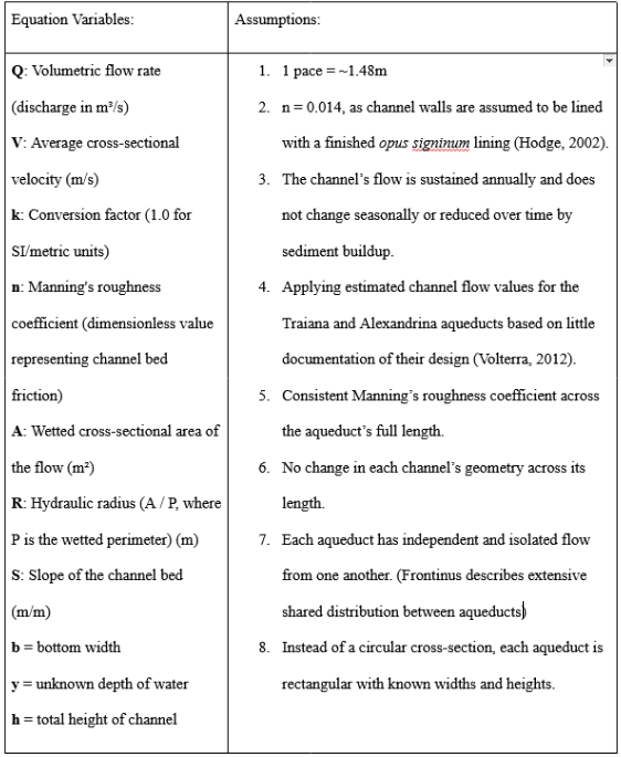
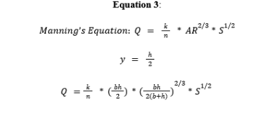
The purpose of calculating the percentage of the specus occupied is to determine typical conditions which the aqueducts operated. Table 2 takes the values from Table 1 and converts them into consistent units used for future calculations. To convert Frontinus’s discharge figures into modern units, a standard conversion of approximately 40 m³/day per quinaria is applied, producing the flow values shown in Table 2 (Hodge, 2002). Lengths and discharge values from Frontinus are applied when available, and gaps of knowledge are filled using modern estimates made about the structures. Using the known values in Table 2, the approximate water depth and percentage of channel cross-sectional area occupied by water can be estimated using Manning’s equation and other geometric formulas written in Equation 2.
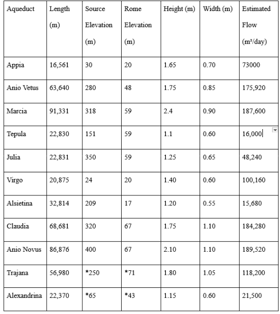

From Table 2, the total water supplied by all eleven aqueducts can be found, in m³/day. This can be then converted into annual water supplied, which will be compared to Seattle’s total demand for future analysis. After summing up flow values, Rome’s water infrastructure delivered 412,486,500m³year to its residents.

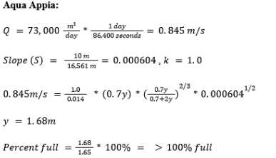
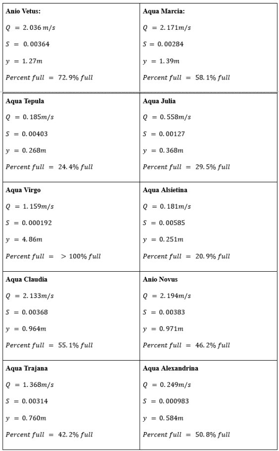
Aqua Appia and Virgo are actually calculated to overflow (y>h), most likely because this method holds many assumptions that end up failing at some point. The most impeding assumption made here is that the aqueduct is one consistent gradient over its entire length. This ignores localized steep segments and changes in gradient that allow the water to speed up. The lower the assumed gradient is with a fixed flow value, the higher the water level will be as it moves slower through the channel. The slope and flow values are working against each other, as a slope of just 0.000604 for Aqua Appia makes the water crawl, meaning the narrow 0.70 meter channel does not have the physical capacity to clear 73,000 m³/day without backing up and spilling over. The eleven Roman aqueducts collectively delivered approximately 412,486,500 m³ of water per year, with calculated water depths within the specus ranging from 21 to >100% of the channel height, demonstrating that the typical dimensions of the channels seemed to purposely never operate completely full. The Romans constructed aqueducts with larger cross-sections than needed to convey their discharge in order to help with maintenance access as well as prevent unnecessary sediment buildup.
Applying Roman Parameters to Seattle’s Demand
The flow rates of the Roman aqueducts provide a useful basis for this analysis comparing ancient vs. modern water-supply systems. The Roman supply + design capacity provides an opportunity to examine how a similarly gravity-driven system could be scaled to meet a modern city’s water demand.
Seattle provides a great comparison because its system also relies primarily on two mountain watersheds: the Cedar River Watershed, 35 miles southeast of Seattle, supplying 70% of the drinking water for the regional system, and the South Fork Tolt River Watershed, supplying the rest from 35 miles east of Seattle (Figure 9). Together, these sources serve approximately 1.6 million people in the greater Seattle area (U.S. Census Bureau, 2020). Based on the 70/30 split between the Cedar and Tolt sources, total municipal demand is approximately 163,037,685 m³ per year, meaning Rome’s eleven aqueducts, at a combined 412,486,500 m³/year, delivered roughly 2.5 times the volume Seattle’s system provides today (Seattle Public Utilities, n.d-a).
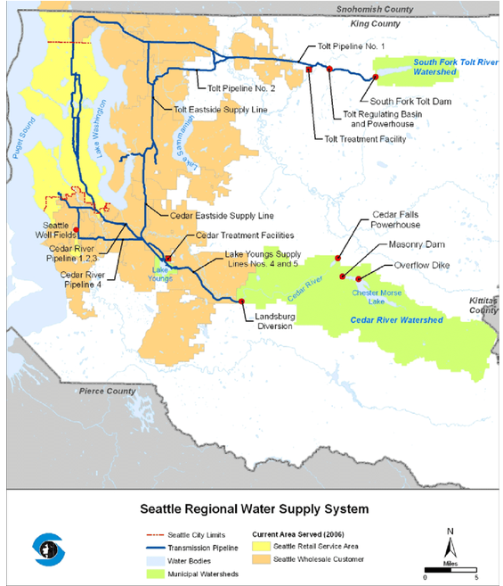
The Cedar supply begins in Chester Morse Lake and the Masonry Pool (Figure 10), where water is stored behind Masonry Dam before entering the Cedar River. The water travels downstream to the Landsburg Diversion Dam (Figure 11), where an average of only approximately 18% of the Cedar River’s annual flow is diverted for drinking water, while the remaining 82% continues downstream to support river and ecological functions before eventually reaching Lake Washington and Puget Sound (Seattle Public Utilities, n.d-b).
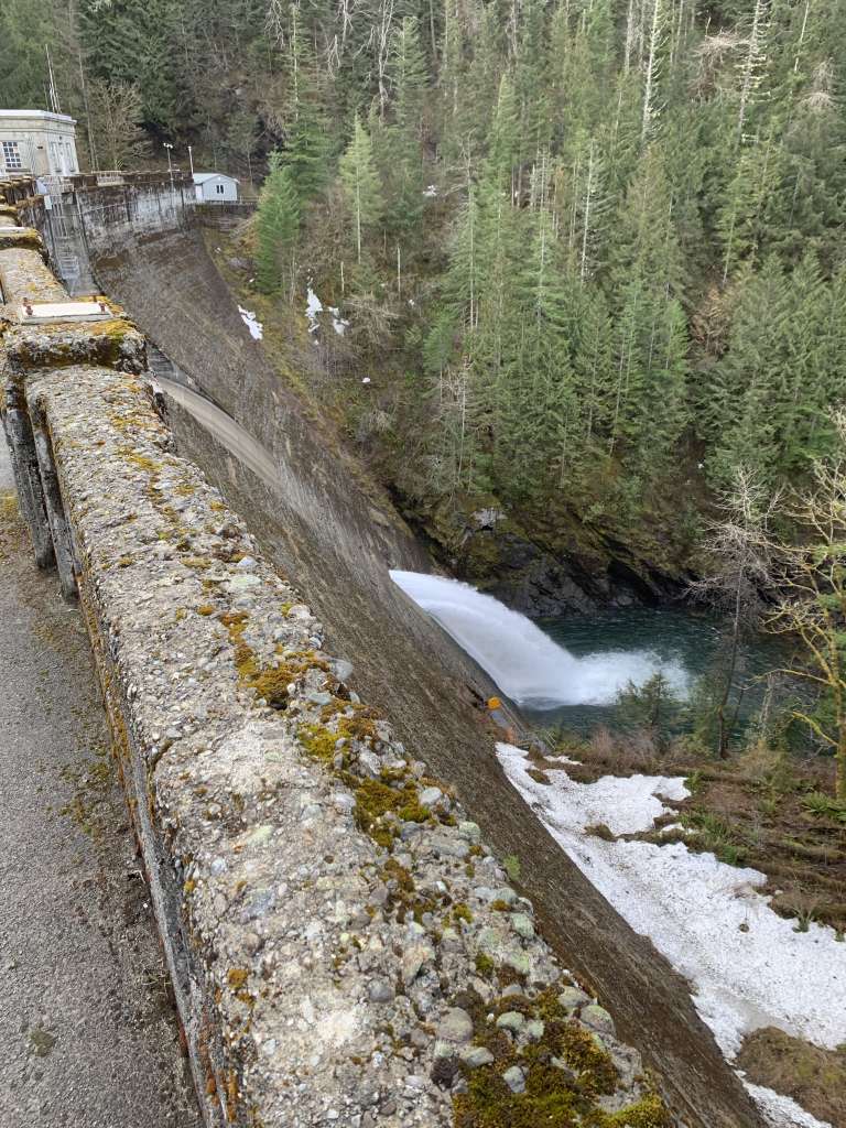
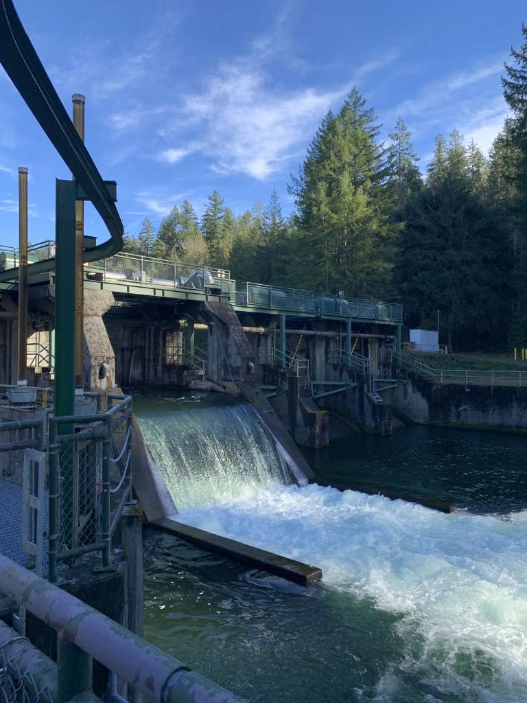
The diverted water is conveyed through two large pipelines for more than seven miles to Lake Youngs Reservoir, where it is subsequently treated before entering the regional distribution system. The Tolt system operates similarly in that water is captured and stored at Tolt Reservoir before being gravity-fed to the Tolt Water Treatment Facility (Seattle Public Utilities, n.d.-c). Thus, although both Rome and Seattle rely on distant sources and elevation differences to move water toward the city, Seattle separates collection, storage, treatment, and distribution into distinct components rather than relying on a single continuous channel.
This system shows many important differences between ancient vs. modern ways of water management. First, instead of diverting most of the river’s flow to the city for consumption, Seattle intentionally limits the amount withdrawn from the Cedar River. The second difference is the processes utilized for water quality treatment. Water collected from the Cedar and Tolt watersheds must pass through intense treatment facilities before being distributed. Cedar River water is treated through chlorination, ozonation, ultraviolet disinfection, fluoridation, and pH adjustment (8.2 target) with lime to reduce corrosion and lead leaching. Tolt water undergoes ozonation, granular-media filtration, pH and alkalinity adjustment, chlorination, and fluoridation. This contrasts with Rome, where the aqueducts primarily functioned as gravity conveyance systems and water was distributed through castella. A third and very important distinction between the systems is the design philosophy and safety margin. Roman engineers lacked the modern mathematics engineers rely on now to calculate precise tolerances, so they compensated by over-designing everything and building beyond the minimum strength/material required. Now, engineering is all about designing close to calculated demand to ensure meeting code-specified safety factors in order to conserve material and capital. This helps understand why the aqueducts could carry more water than what was needed for a modern metropolis: Roman engineers were not just meeting demand, but were building in a margin against uncertainty that modern designs eliminate.
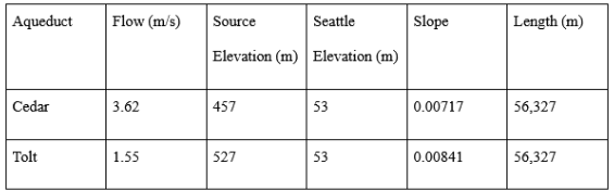
Conceptually, if Seattle’s existing pressurized pipelines were replaced with a Roman-style open-channel aqueduct for each watershed according to their contribution to the water supply (70/30 split), the hypothetical Cedar aqueduct would need to convey approximately 114,126,380 m³/year, while the Tolt aqueduct would need to convey approximately 48,911,305 m³/year. To understand the requirements for the design of these structures, a 50% channel depth and a 1.0 meter channel width will be assumed based on average Roman aqueduct values found previously.
The physical dimensions of these hypothetical aqueducts can then be estimated using the same approach applied to the Roman channels. The average elevation of greater Seattle is 53m, and the starting elevations of the Tolt and Cedar are recorded in Table 5. Each reservoir is located 35 miles from Seattle, so each aqueduct will once again be considered a straight line with a single gradient similar to previous calculations. Using a Manning roughness coefficient of n = 0.014 for a finished opus signinum-lined channel and treating the hypothetical aqueducts as rectangular open channels, channel dimensions can be found. The hypothetical Cedar aqueduct is calculated to be approximately 1.0m wide by 2.39m (7.8 ft) high, while the Tolt aqueduct would be 1.0m wide by 1.14m (3.74 ft) high. These dimensions are here to help demonstrate just how capable the Roman aqueduct system is of carrying Seattle’s modern annual demand.
h (cedar) = 2.39 meters
h (tolt) = 1.14 meters
The Seattle comparison also illustrates why a modern equivalent cannot consist solely of two large aqueduct channels. The existing system uses source reservoirs, diversion structures, treatment facilities, storage reservoirs, transmission pipelines, distribution mains, pumps, valves, and continuous water-quality monitoring as separate components of the supply system. A Roman-style system could reproduce the basic principle of using elevation and gravity to transport water, but it would require additional infrastructure to meet modern drinking-water standards and to accommodate fluctuating demand throughout the city. The comparison therefore demonstrates not only the physical scale of Roman hydraulic engineering, but also the extent to which modern water systems have expanded the function of water infrastructure beyond conveyance alone.
Feasibility Analysis
Building infrastructure like this for Seattle is anything but practical. Gravity flow works well across Rome’s geography, but it struggles badly against Seattle’s terrain which is just constant steep hills and shifting gradients. To move water under those conditions, engineers would face two bad options: design impossibly tall stone bridges hundreds of feet above the city, or dig miles of trenches holding a single constant slope just to reach the watersheds at all. Seattle’s source watersheds each sit roughly 35 miles from the city (Seattle Public Utilities, n.d.-a), meaning a Roman-style system would need two separate gravity-fed arcades threading through that entire distance of hills, ridges, and valleys without ever losing their downward pitch. Additionally, an aqueduct alone cannot meet modern drinking water standards without adequate treatment processes somehow integrated into it.
The location of Western Washington also poses a major safety risk, as Seattle sits near the Cascadia Subduction Zone. In a region susceptible to earthquakes, if one large enough hit the arcades, it could instantly crack and collapse. Unlike modern steel and plastic pipes that can bend under tension like an earthquake, the Roman system would shatter, instantly cutting off the city’s entire water supply. Most of the above-ground arcade structures around Rome were lost due to large earthquakes, which is why many aqueduct monuments only hold a handful of arches before being separated by gaps.
Personal Take
This project surprised me by making me re-understand I have built my life around: efficiency. I have always tried to run my life on efficiency, balancing assignments, hobbies, and other routine tasks so that I could get the most done with the least wasted time or effort. Part of the reason I wanted to become an engineer was because I wanted to help build things efficiently, meeting requirements without exceeding them unnecessarily. Seeing how the Romans designed aqueducts and everything else in daily life ran directly against my ideology: overbuilding is a design failure, not a design choice. This instinct soon changed as I realized: Roman engineers were not inefficient because they did not understand their own system, but were solving a different problem than modern engineers solve. Without the mathematics to figure out precise uncertainty, they ensured that designs lasted centuries, while modern engineering, designed close to code minimums to conserve cost and material, lasts decades. Efficiency is not just minimizing input for a given output, it is matching how much margin you build in to how long the thing actually needs to last and how costly being wrong would be. A short-deadline, low-stakes task probably deserves the lean approach I default to. But a design meant to run for generations might be exactly where the more overbuilt, “inefficient” choice is the smarter engineering call.
Conclusion
So, would a Roman-style aqueduct system meet the water demands of modern-day Seattle? Based on the flow figures calculated, the answer is yes. Rome’s system moved enough water via gravity alone to plausibly cover a modern city ~2.5x the demand of Seattle’s. However, the real question is: Should we actually build it? No. The same properties that enabled these structures to deliver water reliably for hundreds of years are precisely the properties that make them dangerous in a region defined by the Cascadia Subduction Zone. The structures perform poorly during seismic events, offer no filtration, and fail to meet many modern health standards. Ultimately, this paper reveals that while ancient Roman hydraulic principles are perfectly sound from a delivery and longevity perspective, they are incompatible with the safety and structural demands of the modern day. True “good engineering” is not a fixed set of principles, but designs adapted to their specific landscape, environmental risks, and standards for public health. Comparing Rome’s channels to Seattle uncovers the brilliance of the city’s public works, but it also exposes exactly where it fails. As I stood beneath the Aqua Claudia’s arcade in Parco degli Acquedotti, it was easy to believe these structures could do almost anything. Running the numbers and analyzing the capabilities of the system as a whole helps reveal the limit that scale alone couldn’t reveal.
References
Blackman, D. R. (1978). The volume of water delivered by the four great aqueducts of Rome. Papers of the British School at Rome, 46, 52–72.
Blackman, D. R. (1979). The length of the four great aqueducts of Rome. Papers of the British School at Rome, 47, 12–18.
Centers for Disease Control and Prevention. (2024). Risk factors and pregnancy. Childhood Lead Poisoning Prevention.
Chanson, H. (2000). Hydraulics of Roman aqueducts: Steep chutes, cascades, and dropshafts. American Journal of Archaeology, 104(1), 47–52.
City of Seattle GIS Program. (n.d.). Seattle city limits [Data set]. https://gisdata.seattle.gov/server/rest/services/COS/Seattle_City_Limits/MapServer
Deming, D. (2020). The aqueducts and water supply of ancient Rome. Groundwater, 58(5), 662–672. https://doi.org/10.1111/gwat.12958
Dragoni, W., & Cambi, C. (2015). Hydraulic structures in ancient Rome: Mid-week technical field trips, MT1 field guide. 42nd IAH Congress, Rome, Italy.
Frontinus, S. J. (2003). On the water-management of the city of Rome (R. H. Rodgers, Trans.). LacusCurtius. (Original work published ca. 97–104 CE; based on critical edition published 2004 by Cambridge University Press)
Hodge, A. T. (2002). Roman aqueducts & water supply (2nd ed.). Duckworth.
Klaassen, R. (2016). Roman water supply – Romeinse waterleiding.
Roma Capitale. (2022). Aqua Virgo Park. Turismo Roma.
Seattle Public Utilities. (n.d.-a). Water system. City of Seattle.
Seattle Public Utilities. (n.d.-b). Cedar Water Treatment. City of Seattle.
Seattle Public Utilities. (n.d.-c). Tolt Water Treatment. City of Seattle.
Seattle Public Utilities. (n.d.-d). Water supply & treatment. City of Seattle.
U.S. Census Bureau. (2020). 2020 Census: City of Seattle, Washington. U.S. Department of Commerce.
Volterra, V. (2012). The Aqua Traiana. Journal of Roman Archaeology, 25, 345–362.